Space In A Box: The Battery Board

It’s time to assemble our CubeSat’s power management system
This post is sponsored by PCBWay, a leading small circuit board manufacturer. We’re excited to partner with PCBWay to showcase their high-quality prototyping services. If you’re looking for reliable, fast, and affordable PCB prototyping, use this link to check out PCBWay and earn bonus credit for your next project!
In this previous article, we kicked off construction of the CubeSat simulator series. A joint project with our friends at PCBWay, the simulator uses an open-source design that was created by the Radio Amateur Satellite Corporation (AMSAT).
Fitting into a 1U cubesat design, the boards aim to leverage open-source hardware like the Raspberry Pi to help teach fundamental skills about radio frequency design and application.
The good news is that our circuit boards are here, however, some components that are needed for the main board are still in transit. Because of this, we’re going to move ahead and construct the battery board and return to the main board when the last of the components have arrived.
With that said, let’s take a look at the schematic for the battery board to see what we’ll need to do to complete it.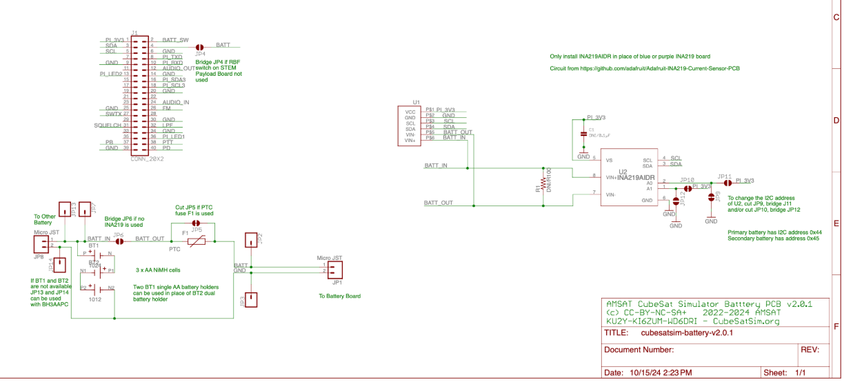
And here’s our bare battery board that was manufactured by PCBway. In the interests of keeping things streamlined, the design files differ slightly from the original AMSAT design, but the fundamentals of the project remain the same.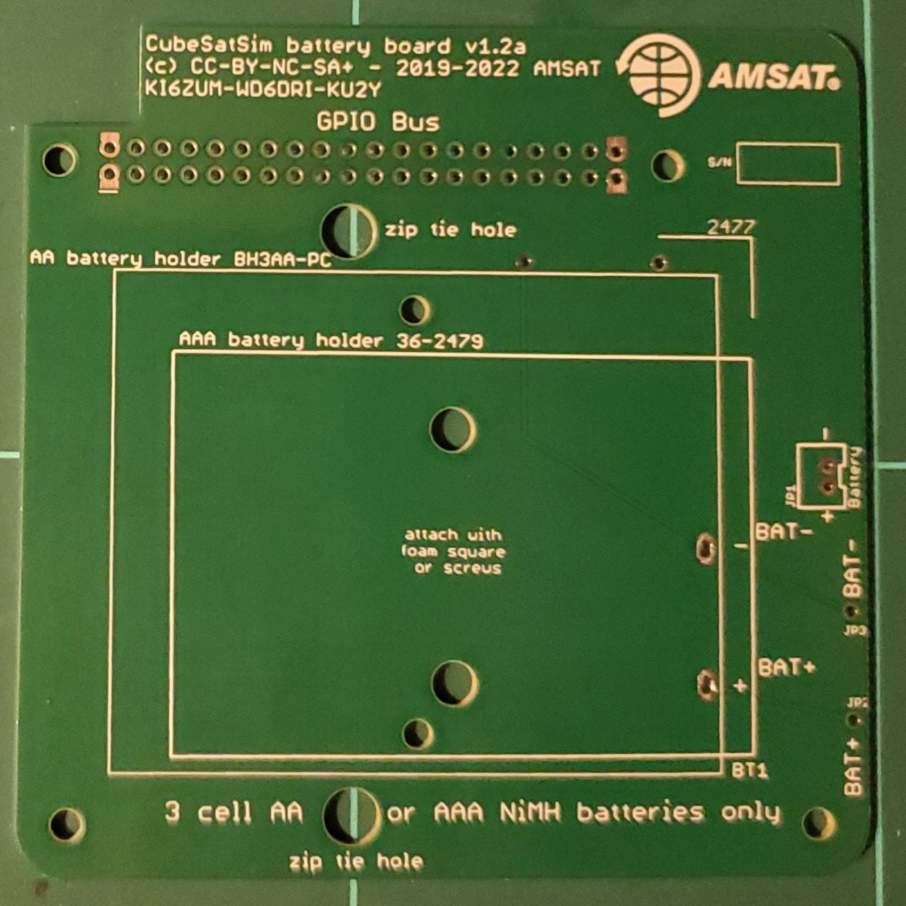
Even though the designs are uploaded as ready-to-go and open-source, it’s still worth double-checking to ensure everything is laid out correctly. And when we did this, the excellent quality control team at PCBway identified some minor changes that would enhance the main board. We elected to implement these changes at the production stage, so our main board will look a little different to the one in the Wiki.
This is also a useful service for your own projects, as it can make troubleshooting a design before production much easier. We’ll be looking at the production process of our boards in an upcoming feature article and highlighting some of the design support that you can get with your own prototypes.
Power Management & Storage
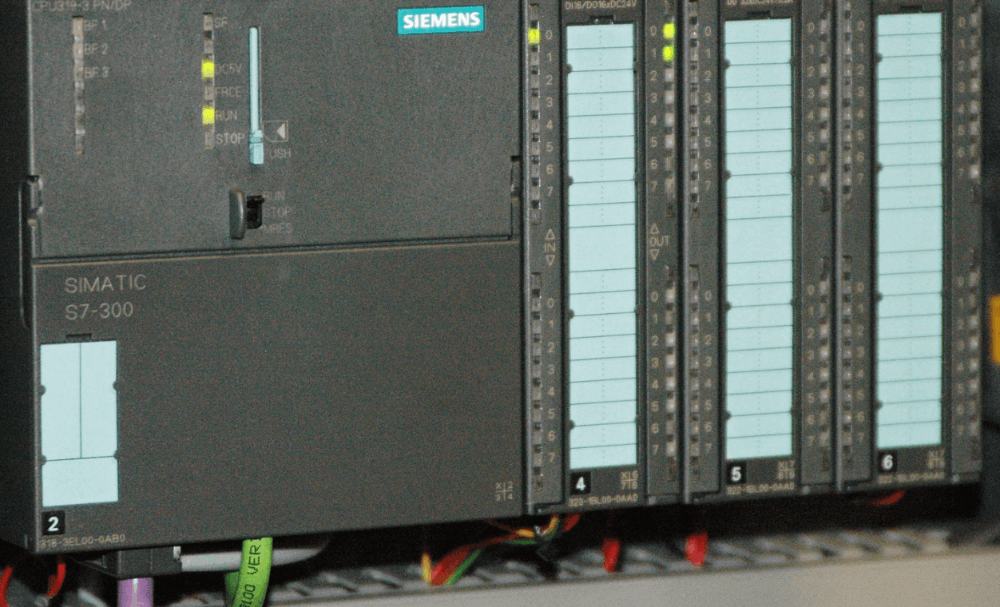
It’s fair to say that for this project, the majority of the smarts are in the main board, as well as the Raspberry Pi Zero that is to be used as the flight controller. As such, the main board is the most heavily populated board, containing the RF circuitry, antenna connectors, and Raspberry Pi Pico to run the BME-280 sensor and other payloads.
While this means the main board has some pretty interesting demands regarding successful construction, the alternative side of this is that the other two boards (Battery & Solar) are relatively simple to assemble.
The battery board in this instance has just ten components that we’ll need, and some of those are the cable ties that are used to keep the battery in place. It’s this simplicity that makes the simulator a great educational project, as you won’t need pro-grade soldering skills to get things assembled.
Here’s our bill of materials that we’ll need for this stage of assembly.
Assembly
The Battery Board stacks on top of the Pi Zero and under the Main Board, which means we’ll need to give it a set of headers so everything passes through properly. We’ll also need to ensure that we keep things nice and clean during construction so that everything stacks correctly.
Our first step is mounting the headers to our INA219 current sensor. This will allow us to mount it to the board to keep everything regulated. Then, we’ll need to bridge jumper A1 to ensure we’ve set the correct I2C address for the sensor.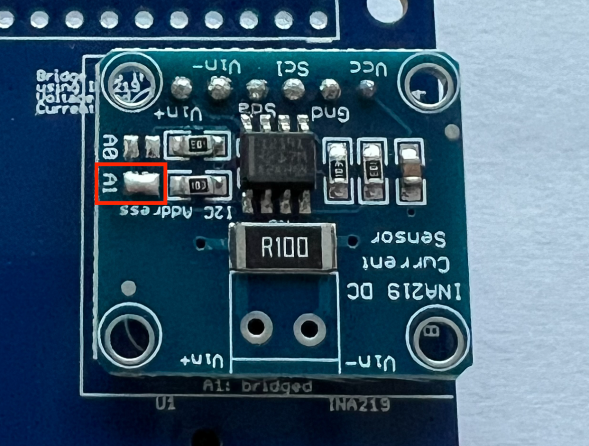 Jumper A1 will ensure the correct address is set for the board. Source: github.com
Next, we’ll solder the battery holders to the board, being careful with our heat levels to ensure damage-free assembly. We’ll also need to ensure there’s enough space left on the board to pass through the cable ties that will be used to keep the batteries securely in place. This is where our design differs slightly, as rather than using two battery holders, we’ve stuck with one double battery holder.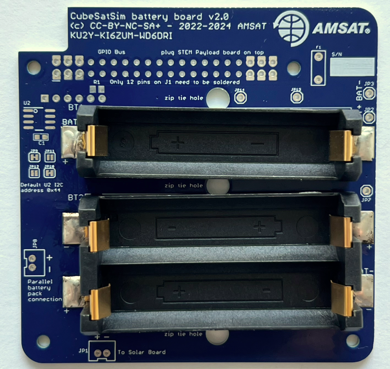
Once this is complete, the final step is to install our JST connector to the board. With this, we can pass the power we generate from the Solar panels back into the Battery board for storage.
While this is a relatively simple circuit, good practice dictates that we verify polarity and ensure the correct installation of components on the circuit board.
When this is complete, our battery board should look something like this. The assembled board looks a little different from the one in the Wiki, but we’re still good to go. Source: Wikipedia
Next Steps
With the completion of the battery board and the programming of the Pi software also complete, we’re now more than a third of the way through the project. Over the next month, the next job will be to work our way through the final two sections of the main board.
From there, we can carry out the initial testing to ensure that the construction of the board has been completed correctly and that the main board is communicating properly with the Raspberry Pi flight controller.
Then, we’ll have to give it the smarts it needs to generate and manage all the onboard power it will need to complete a successful “mission”.
While this might all sound pretty complex, the reality is that the modular design of the simulator makes the testing phase quite straightforward. But, to see if things play out like this, you’ll have to continue reading next month!
Build Your Design
As Radio Hackers grows, it also expands, and the CubeSat simulator is just the start of this expansion. Over the next few months, we’ll be implementing some changes that will help make it easier to bring new projects from concept to working prototype and acquire new hardware at a discounted rate, where needed.
Aligning with partners means that we can continue to bring you plenty of interesting projects to read about. More importantly, these partners will also bring perks that will benefit readers directly.
The long-term aim is to turn the publication into a one-stop maker shop, where you can document your project while building it, using trusted publication partners to keep everything easy and low-stress.
Are you up for the challenge?
If you found this article insightful, informative, or entertaining, we kindly encourage you to show your support. Clapping for this article not only lets the author know that their work is appreciated but also helps boost its visibility to others who might benefit from it.
🌟 Enjoyed this article? Join the community! 🌟
📢 Join our OSINT Telegram channel for exclusive updates or
📢 Follow our crypto Telegram for the latest giveaways
🐦 Follow us on Twitter and
🟦 We’re now on Bluesky!
🔗 Articles we think you’ll like:
- What The Tech?! Space Shuttles
- Shodan: A Map of the Internet
✉️ Want more content like this? Sign up for email updates