The CubeSat Simulator: STEM Board Development

This article is sponsored by our partners at PCBWay. Talk to the team to get design support to help bring your next project to life.
As we’ve progressed through building the cubesat simulator, we’ve built out the solar and battery boards, printed our frame and configured the software that will help make the whole thing work.
As such, we’re now in the final stages of the project, and all that remains is assembly of the STEM board before we move the unit into the studio for final pictures and testing of the onboard RF-based payload.
Let’s start by taking a look at the components on our next board and having a quick chat about the development process for projects like this one.
Share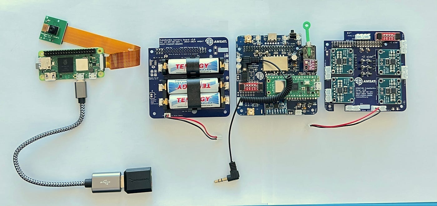 Our v1 boards differ slightly from the updated v2 boards. Source: github.com
Checking Is Good
The latest variant of the cubesat simulator has been streamlined to improve both power efficiency and overall reliability. This would be done by targeting simplicity, with the Pi Zero running the cubesat hardware while the Pi Pico enabled a near plug-and-play design that works with the sensor board. RF transmission duties would be handled by the SR105U chipset. This overall configuration would give us a v2.1 Cubesat Simulator.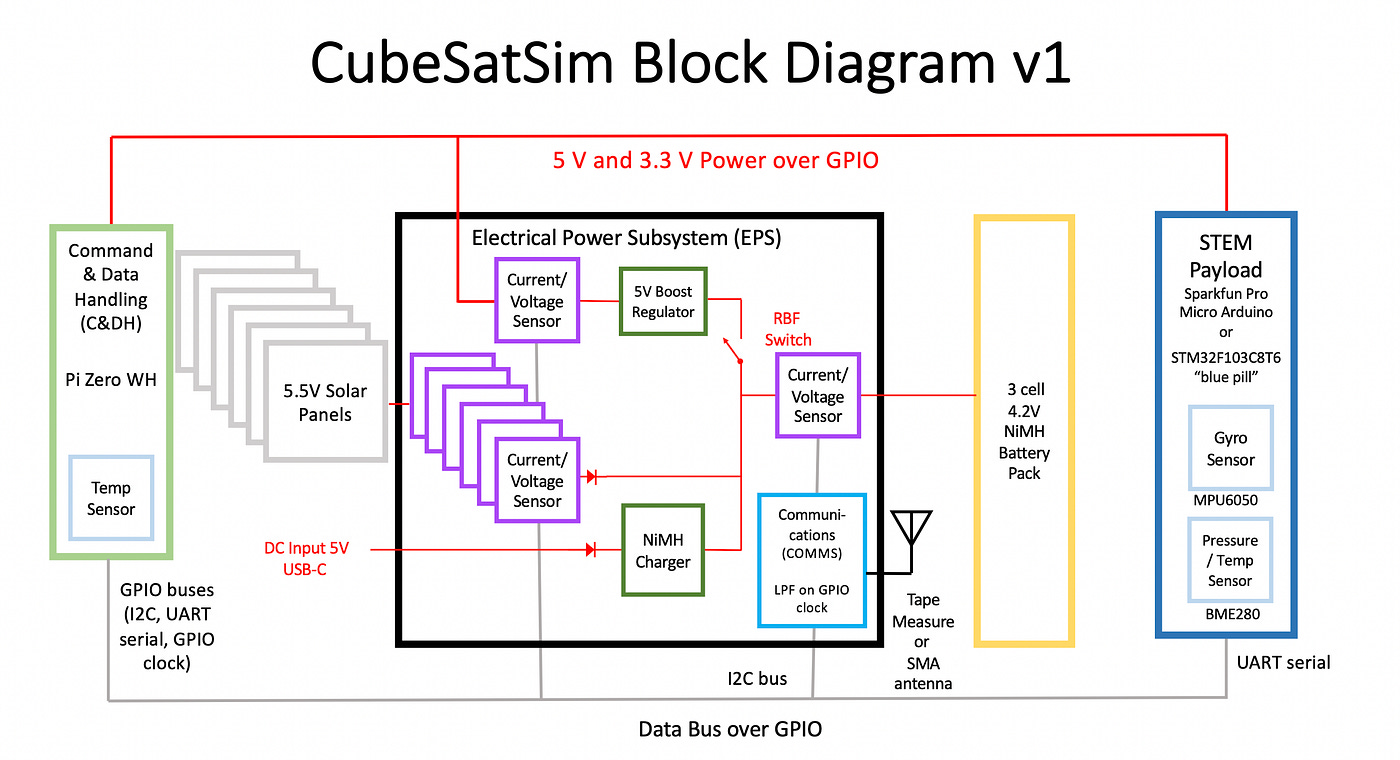 The Block Diagram helps to highlight the differences. Source: github.com
This is all fine and good, but our boards are the earlier v1.3 variants, making them slightly different to the later versions. Rather than running the payloads off a Pico, we’ll use an STM32 to obtain data from our Gyroscope (MPU6050) and Temp (BME280) sensors.
This is a pretty straightforward change, but it’s a great reminder that building isn’t as simple as downloading some plans and throwing them together. For most projects, troubleshooting and adapting to problems is often the difference between failure and success.
Note: Our main boards used a modified trace for increased reliability, thanks to the recommendation of the PCBway support team. While this is great for the end design, it ended up being terrible for photography. In the interests of keeping things visible and easy to follow, some images are extracted from the CubeSat Simulator Wiki.
The Assembly Process
Unlike the earlier boards, our STEM board is built in a single sitting before we configure the payload sensors. In terms of difficulty, the STEM board is the most complex to assemble, as it will entail the addition of code after the hardware construction is complete.
However overall, it’s still a reasonably simple design, as it mostly uses through-hole components. With that said, let’s check out our schematic.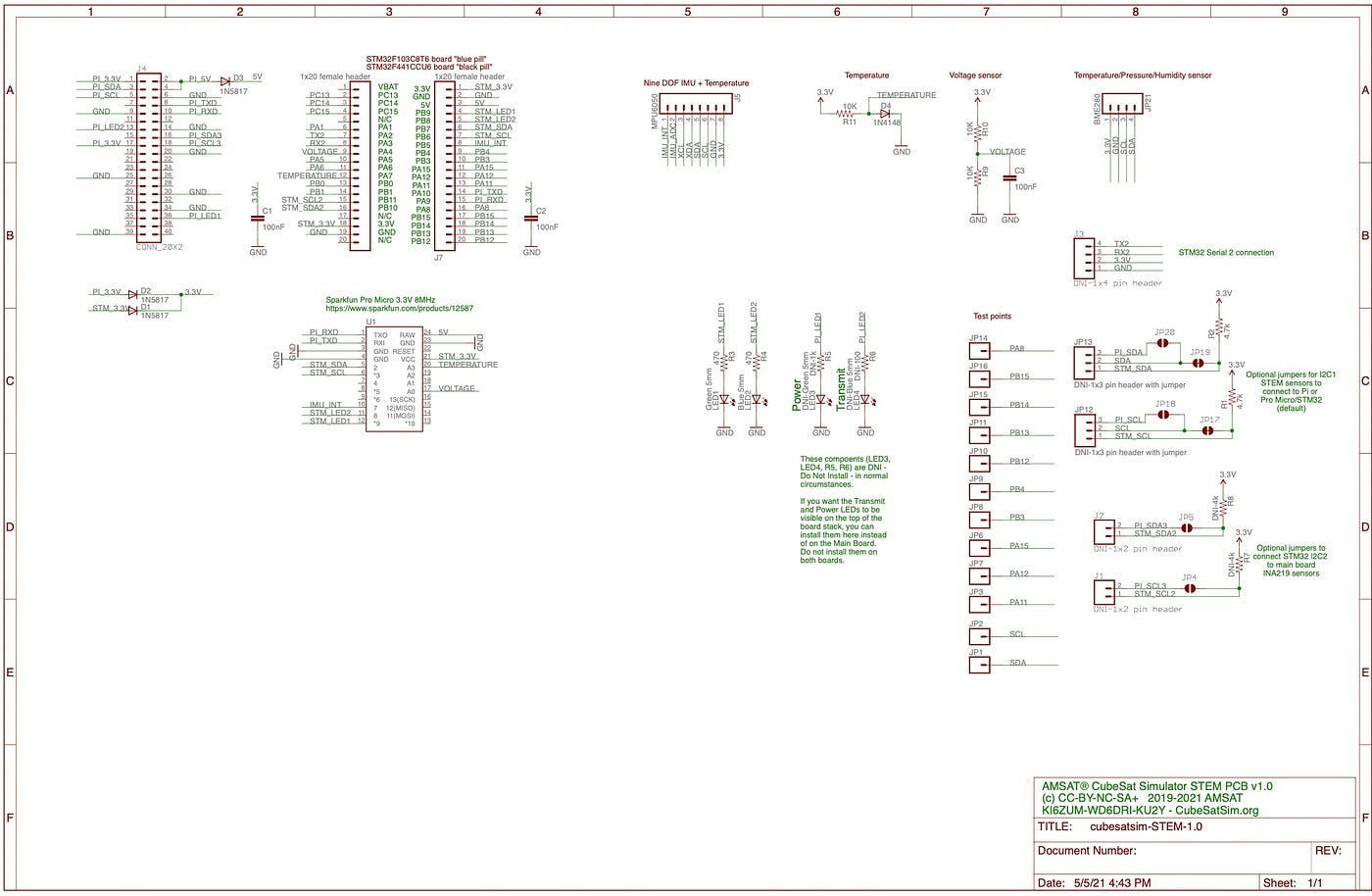 The helpfully included schematic helps to make the installation of the components trouble-free. Source Github.com
We have headers for our STM32 & sensors as well as some diodes, LEDs and resistors. There’s also the main GPIO bus that enables all three boards to interlink correctly.
The biggest challenge here is ensuring the correct stand-off distances for the headers. Failing to do this correctly means that at the end of the project, the boards will not stack correctly. A quick look at the finished stack shows us that the STEM board is on top.
So, before soldering the main bus, we’ll need to check to ensure that there is enough stand-off distance to maintain correct spacing.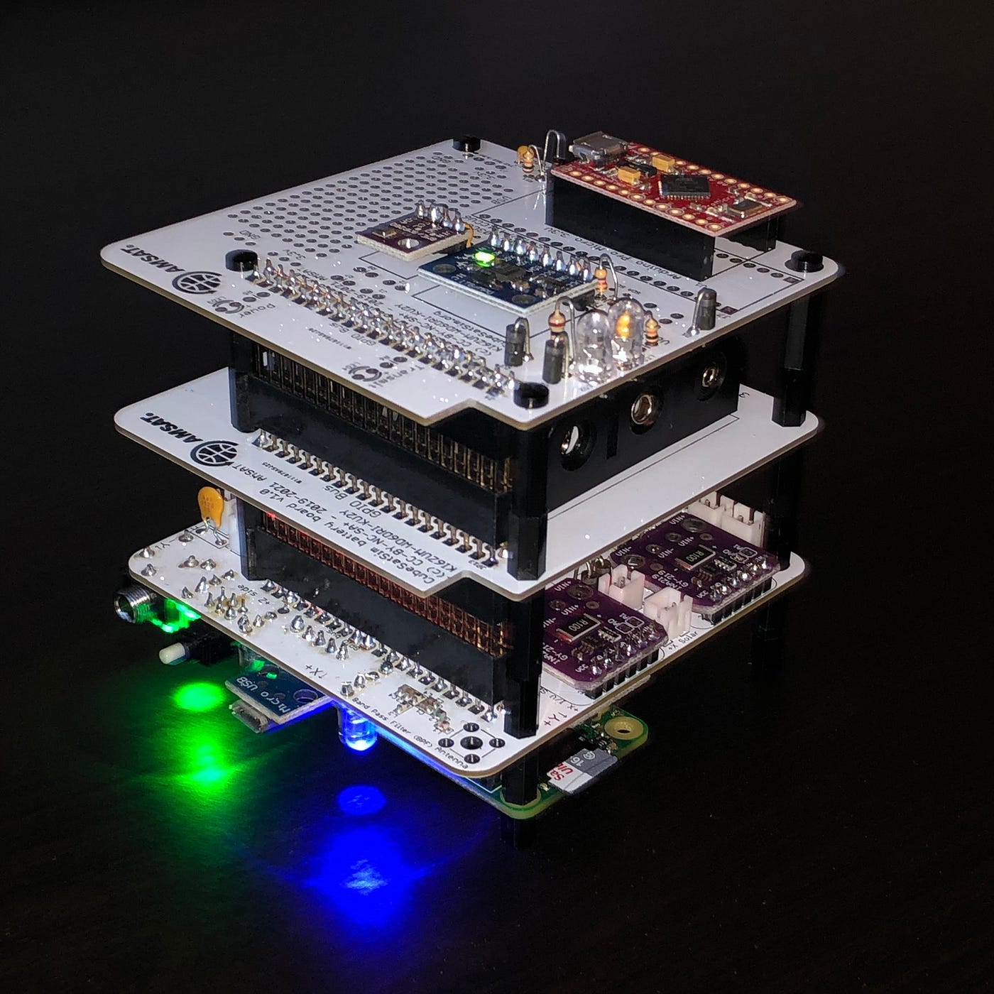 The main GPIO bus will not install correctly if it is not soldered properly. You’ll also need to ensure appropriate stand-off space for the other boards. Source: Github.com
Once this is done, we’ll install the diodes next. These ensure that our payload can run correctly from the Zero’s GPIO pins while preventing the Pi from obtaining power via the microcontroller’s USB port. Three 1N5817 diodes in locations D1, D2 and D3 will take care of this. The grey band on the diode will help us identify the correct polarity.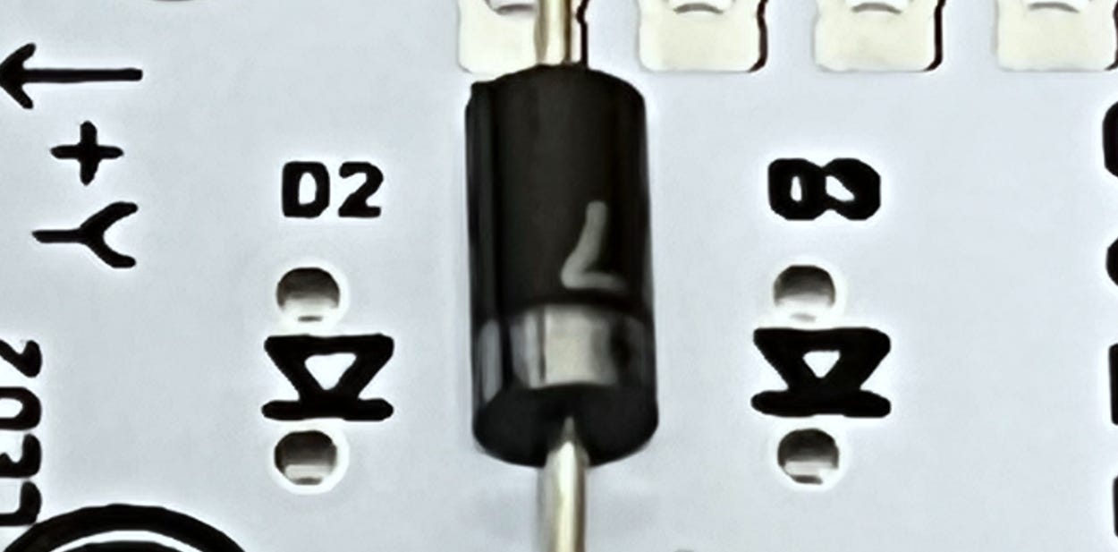 The good old 1N5817 is put into service here. Source: Github.com
Next up are our resistors and LEDs. There are two 4.7k resistors (yellow violet red colour bands) in locations R1 & R2, followed by a 1k resistor (brown black red colour bands) in location R3.
Last up are our LEDs. Correct polarity is important here too. The longer leg of the LED indicates +, which will be mated to the + outlet on the STEM board.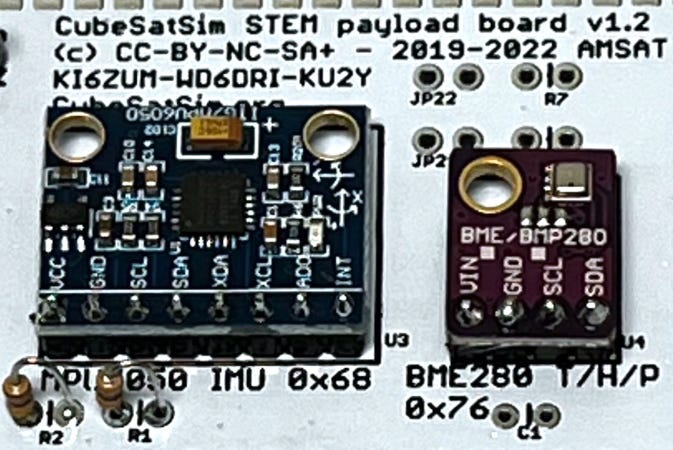 Fina I2C allocation will occur when we upload the code into the STM and carry out the testing. Source: Github.com
Once this is complete, we’ll solder the header pins to our sensors so they can be installed onto the board. Then, we’ll add the sensors onto the board.
The final part of the process is a partial power-up. Here, we can test that the components are correctly installed and working properly. We can also ensure that the microcontroller board and payload sensors have no configuration issues.
To do this, we’ll simply apply power to the microcontroller’s USB port. If everything lights up as our board did, that can only mean one thing.
We’re ready to go!
Check out AMSAT’s testing of the STEM board in this video if you need assistance troubleshooting.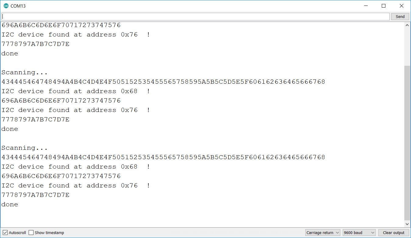
The End Days
From a maker’s perspective, the construction stages of the process are almost complete. On the payload side, all that remains now is to upload the payload code into our microcontroller and check the final configuration of the I2C bus to ensure the sensors are working correctly with the correct address assigned.
We’ll also add an external filter inline to the antenna output to ensure our board is emitting a clean signal that contains no spurious emissions.
Once this is completed, we can assemble the final stack into our 3D-printed frame and add our solar panels to complete the power generation system.
We’re all about the education here, so once the Simulator passes this final stage of the test process, it should be heading off to a local school to end up in the science department.
Here, it will be used as an educational outreach tool to teach students about the CubeSat format, RF systems and hardware development.
Want to build your own CubeSat Simulator as well? Keep an eye out, because at the end of the series, we’ll be giving away a set of boards that you can use to build your own project.
Alternatively, if you have a fresh design of your own that you’d like to bring to life, be sure to contact the team at PCBWay to get design support from iteration through to production, as well as a welcome bonus to kick your project off.
Subscribe now
If you found this article insightful, informative, or entertaining, we kindly encourage you to show your support. Clapping for this article not only lets the author know that their work is appreciated but also helps boost its visibility to others who might benefit from it.
🌟 Enjoyed this article? Join the community! 🌟
🐦 Follow us on Twitter and
🟦 We’re now on Bluesky!
🔗 Articles we think you’ll like:
- What The Tech?! Space Shuttles
- Shodan: A Map of the Internet
✉️ Want more content like this? Sign up for email updates