Semiconductor Diode Experiment
Exploring Semiconductor Junction Diodes: An In-Depth Experiment
Introduction:
Semiconductor junction diodes play a crucial role in electronic circuits, allowing current flow in only one direction. This experiment aims to delve into the characteristics of diodes, focusing on V-I (voltage-current) curves and exploring the properties of zener diodes. By utilizing various equipment and components, participants will gain hands-on experience and insights into the behavior of semiconductor devices.
Components and Equipment:
- Digital Multimeter (DMM)
- DC Power Supply
- Signal Generator
- Oscilloscope
- 1N4148 Diode
- Zener Diode
- 1K Resistor
Theoretical Background:
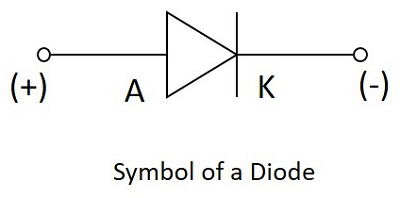
Diodes are semiconductor devices with the ability to allow current flow in one direction. Composed of a p-n junction, they are made from materials with positive (p-type) and negative (n-type) doping. Silicon diodes typically have a barrier potential of 0.7 V, and they conduct current when the anode voltage is 0.7 V higher than the cathode.
Zener diodes, designed to leverage the Zener breakdown region, exhibit a constant breakdown voltage, making them essential in regulated power supplies.
Experiment Procedure:


- Diode Test:
- Use the diode-testing scale on the DMM to determine diode conditions.
- Perform tests for the Si diode, checking forward and reverse bias.
- Diode Characteristics:
- Build a basic diode circuit and measure diode voltage as the power supply varies.
- Calculate diode current and plot the V-I characteristic.
- Draw a tangent line and determine incremental resistance.
- Zener Diode:
- Replace the diode with a Zener diode in the circuit.
- Measure diode voltage, calculate diode current, and plot the V-I characteristic.
- Apply negative voltages and record results.
Experiment Procedure:
Note: Before starting the experiment, ensure you have received proper instructions from the instructor.
1. Diode Test
1.1. Diode Testing Scale:
- Set the DMM to the diode testing scale.
- Connect the diode as per Figure 5 for Si diode testing.
- Record readings for both forward and reverse biases in Table-1.
- Analyze the results to determine the diode's condition.


1.2. Resistance Scale:
- Use the resistance scale on the DMM.
- Connect the diode to measure resistance levels in forward and reverse biases.
- Record readings in Table-2
.
2. Diode Characteristics:
2.1. Basic Diode Circuit:
- Construct the circuit shown in Figure 6.
- Gradually vary the power supply voltage from 0 to 10 volts.
- Record Diode Voltage (VD) and Resistor Voltage (VR) for each step in Table-3.
- Calculate Diode Current (ID) using Ohm's Law (ID = VR / R1).


2.2. V-I Characteristic:
- Plot the V-I characteristic graph with Diode Voltage (VD) on the x-axis and Diode Current (ID) on the y-axis.
- Draw a tangent line to the curve around 3mA ID and determine the incremental resistance using the given formula.
3. Zener Diode:
3.1. Basic Zener Diode Circuit:
- Replace the diode with a Zener diode in the circuit (Figure 7).
- Follow the same steps as in the basic diode circuit.
- Record results in Table-4.
3.2. Negative Voltages:
- Apply negative voltages (as given in Table-5) to the Zener diode circuit.
- Record results for Diode Voltage (VZ), Resistor Voltage (VR), and Diode Current (IZ).
- Analyze the Zener voltage characteristics.
3.3. V-I Terminal Characteristic:
- Utilize data from both positive and negative voltage ranges.
- Plot the complete V-I terminal characteristic for the Zener diode.


Answers:


#ElectronicsLab #DiodeCharacteristics #SemiconductorDevices #ExperimentalPhysics #ElectricalEngineering #CircuitAnalysis #HandsOnLearning #EngineeringEducation #STEMExperiment #DiodeTesting #ZenerDiode #VICharacteristic #DigitalMultimeter #Oscilloscope #PowerSupply #SignalGenerator #STEMEducation #ElectronicsExperiment #SemiconductorJunctionDiodes #ExperimentalDesign #EngineeringLab #OhmsLaw #IncrementalResistance #ZenerBreakdown #ElectronicComponents #ScienceBlog #STEMDiscovery #ElectronicsInPractice #LabProcedure