Software Defined Radio & Radio Hacking: Radio Direction Finding

Discussing the Concept and Importance, of Radio Direction Finding
In Part 1 of this article, we looked at the relevance of SDR in cyber security and other roles. Today’s article is Part Two of the series and is a focus on direction finding and Geolocation of signals. It’s a lessor skill in regards to cyber security but it is an important skill with regards to isolating signal interference and under standing how to track and locate signals as required. It’s also still commonly used today, being important in space exploration, search and rescue operations as well as having a valid military applications.
Being based around physics, some of the fundamentals are older yet proven concepts but when that’s paired with modern technology we can still have some great fun with it. It’ll also be a longer article today as there’s several important concepts to impart. Let’s get started.
\
The History:
Discovered in the early 1900’s it took wartime innovation to bring direction finding techniques and strategy into mainstream research. Early radio pioneer Guglio Marconi was involved in discovering key fundamental techniques, however like most early technology these were rudimentary and took time to evolve.
An important part of researching the new technology occurred when the British established a chain of direction finding stations on the coast, targeting German U-Boats allowing proper techniques to be used and refined. This technology was further refined during WW2 with the addition of radar. This eventuated in a system known as HF/DF or “Huff Duff”. Huff Duff focused on German High Frequency radio transmissions and it’s installation on to most allied ships caused significant disruption to the U-Boats, with fresh positions being able to located every time a boat would transmit.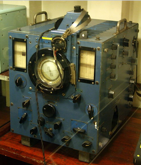 FH4 system, affectionately known as Huff Duff. Source: Wikipedia
Direction Finding was also a key part of safe aviation navigation in the days before GPS, with Non Directional Beacons and VHF Omni Range systems allowing aircraft to navigate the skies with surprisingly good accuracy.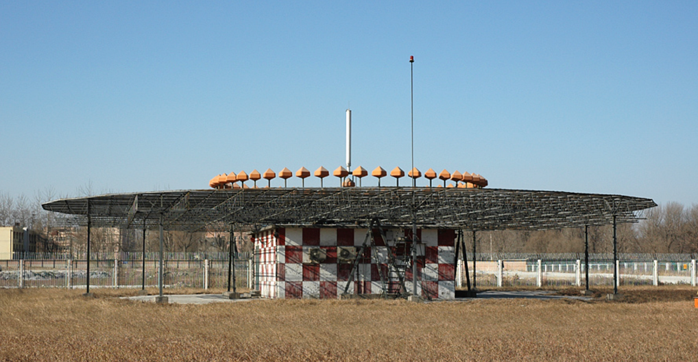 VHF VOR aviation navigation station. Source: Wikipedia.
The Strategies:
While direction finding sounds pretty complicated it’s actually far easier than you’d think. It’s also a great exercise for those getting started with Radio in general, as to DF something successfully you’ll need to understand concepts relating to signal propagation, signal strength and signal type, as well as the concept of harmonic frequencies and how they work. While professional systems may use some of the methods below, beginners can get started with nothing more than a receiver with a good antenna. It’s important to understand the limitations that will come with that however, as usually the less technique you’re using the longer it will take to DF your chosen signal. However a beginner can get started with the basics to get a feel for it as needed.
Firstly though, we need to understand how your receiver antenna radiates and by default, will receive. If you have an omni directional antenna, the pattern will look like this doughnut on the left side of the diagram.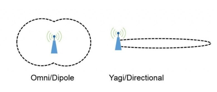 Different Radiation patterns will work to your advantage. Source: Wikipedia
Where as if you have a directional antenna such as a Yagi, your radiation pattern will look like this narrow one on the right instead.
Understanding these patterns are important. This is because as we develop our techniques we can use different types of antennas to DF quickly and more efficiently. While you won’t necessarily need them for today, it is important to understand these concepts early.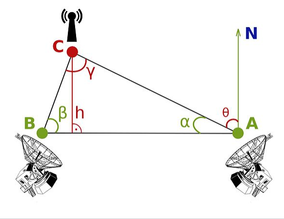 Triangulation merely relies on plotting bearings on your map. It’s the best way to start. Source: Wiki
Triangulation:
Triangulation is one of the fundamental ways to DF a signal, requiring little more than a bearing for your signal and a map to plot it on. Triangulation works best with multiple receivers, however should you only have one you can use a single receiver and change positions to get a fresh bearing instead.
To triangulate you’ll tune your receiver to your frequency of interest, and then turn slowly in a 360 degree circle. To find your bearing correctly, use the onboard compass on your smartphone to obtain an appropriate fix. Where the strongest signal is is the most likely bearing for the signal. Plot that on your map. You’ll need an additional two bearings to properly triangulate but once you have them, the point on your map where the three lines overlap is where your transmitter is.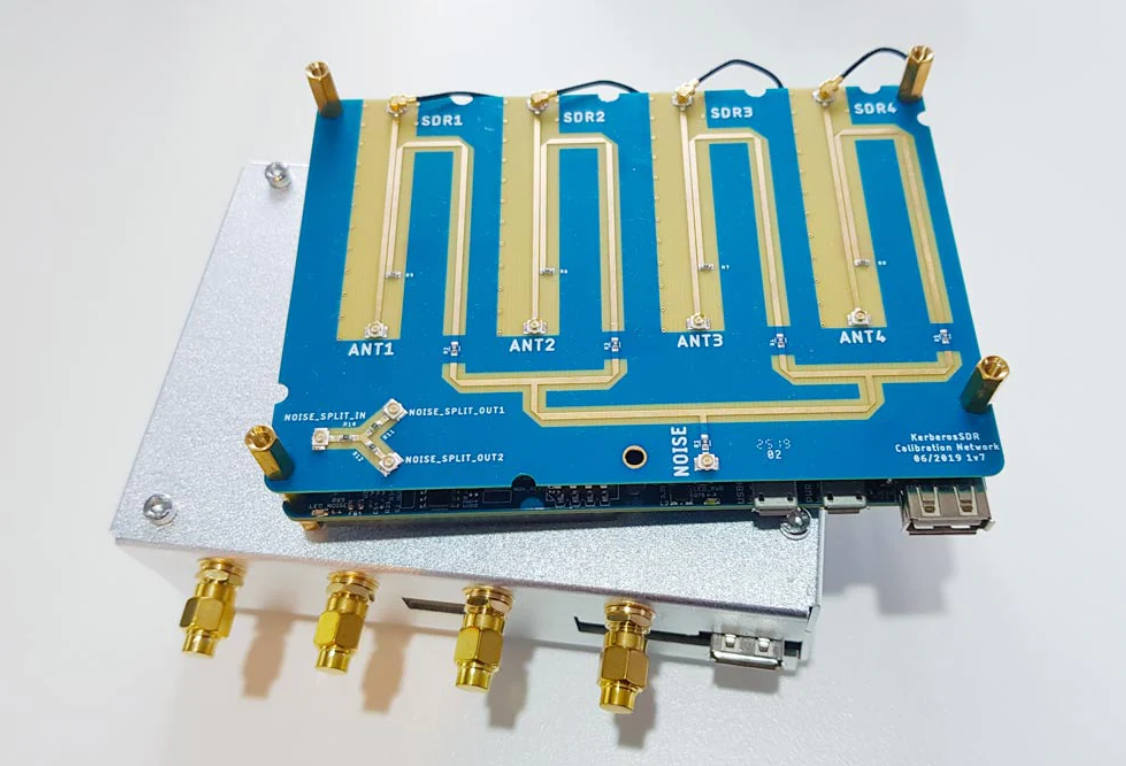 Kerberos SDR uses 4x RTL as receivers along with smart software for TDOA applications. Source: rtlsdr.com
Time Delay On Arrival (TDOA)
TDOA is a more advanced version of triangulation that uses time delay of reception between receivers, along with some smart software processing to calculate a fix extremely quickly. Quite common in military applications TDOA is also common in the civilian research, with a number of off the shelf systems available for purchase.
TDOA is also pretty impressive as a system, as in typical systems the delay can be mere milliseconds, with the processing power doing the heavy lifting with regards to isolating the signal and geo location.
Depending on your level of capability with hardware hacks, a TDOA system is a great RTL project, with many systems having been designed and hardware cheap and readily available.
Should you decide to build a TDOA system, you’ll gain detailed experience on configuration of RTL-SDR dongles, programming of the GUI to receive and process the signals as well as antenna experience, bringing the whole system together.
While it may be out of reach for beginners, experienced hackers and makers can have a great time with a project like this.
Check out this blog post on building a TDOA system, or find a commercial option off the shelf via this link instead. There’s also a super interesting thesis on the RTL-SDR as well.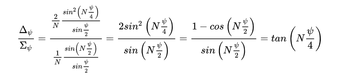 There’s math for TDOA & Phase. Lots and lots of math. Thankfully, we delegate. Source: Wikipedia
Phase Comparison
The last of our common techniques, Phase comparison is similar to TDOA however rather than taking our measurements at the receiver, we’ll apply them at the antenna. Like TDOA, most of the magic is within the software however that processing power enables the rapid geo location of signals with ease.
The basic concept of the method involves measuring the offset between antennas and using this math to apply a bearing to the received signals. Phase comparison is often used in both aviation and military applications and while there’s better ways for researchers to DF signals locally, it’s still a fundamental concept that should be understood.
Challenges and Limitations:
While this sounds like a lot of information to start with, it’s important to realize that TDOA and Phase calculation aren’t really the best way to get started for beginners. The best way to get into this type of thing is to use your RTL to explore the spectrum and develop an understanding around triangulation and plotting RF Data.
One thing you will have to deal with as part of this however is isolating interfering signals and more importantly dealing with an overloaded receiver. This is where understanding the spectrum can come into play as we are able to add, and modify devices to deal with this. The obvious rule of thumb where signal strength increases close to antenna proximity means that eventually you’ll reach a point where you need at attenuate the signal to continue to close in on the location.
The simple addition of a directional antenna will give a significant improvement to any triangulation DF system as it will enable more precise bearings as well as having a significant “null spot” to the sides allowing for better isolation. Designs exist for cheap, easy home made tape measure antenna’s that can allow you to experiment with this some more.
Frequency Harmonics:
Harmonic frequencies refer to unwanted additional frequencies that are generated at integer multiples of the fundamental frequency being transmitted. These harmonics can result from imperfections or nonlinearities in the transmitter’s electronic components, such as amplifiers and oscillators.
For instance, if a radio transmitter is intended to broadcast a signal at a specific frequency, say 100 MHz, due to imperfections in its components, it may also unintentionally emit energy at multiples of this frequency, such as 200 MHz (2nd harmonic), 300 MHz (3rd harmonic), and so on. These harmonic frequencies can interfere with other radio communication systems and can potentially violate regulatory limits set by authorities to prevent electromagnetic interference.
For direction finding purposes, we can use these harmonics as a cheap form of attenuation when attempting to DF an elusive signal. Monitoring the weaker second or third harmonic, will allow you to track a signal far closer than tracking it on the fundamental frequency.
Something to Remember:
Before we close today’s article it’s important to understand that certain parts of radio theory can take significant time to learn and understand. We’ve tried to break that down in to beginner sized portions, allowing people that may be unfamiliar with the spectrum to get involved and start experimenting. Unfortunately because of this, we’ve had to select the bits of the theory side to leave out, so the article doesn’t turn into a novel.
So you may find alternate ways of locating a signal, or different antenna types relating to Direction Finding and that’s entirely okay because like anything, there are many effective ways of doing this. We’ve simply tried to break it down enough for you to get started. Once you’re away, we’d recommend continuing your research so you develop your spectrum knowledge, as large parts of the spectrum remain open to cyber security research. These are often less popular than more common roles meaning there’s plenty to discover in the way of exploits and hardware.
Looking to exploit Bluetooth? SDR. Looking to reprogram an electronic billboard, or intercept data from devices in the ISM bands. SDR. Looking to conduct research into automotive systems or IOT devices. SDR. And best of all, do you want to move from passive signal reception to offensive red teaming?
You got it. You’ll need an SDR.
Remember, there’s a vast array of devices, formats and transmission types in the SDR world and it’s up to you, the radio hacker to ensure you continue take the next steps in discovering them.
Part 3 will focus on intercepting Space Communications & Satellites, but if you’d like to read about another specific SDR topic, feel free to nominate one in the comments. There’s also a separate article on some simple antenna designs to affordably improve your SDR reception coming in the future as well.
Medium has recently made some algorithm changes to improve the discoverability of articles like this one. These changes are designed to ensure that high-quality content reaches a wider audience, and your engagement plays a crucial role in making that happen.
If you found this article insightful, informative, or entertaining, we kindly encourage you to show your support. Clapping for this article not only lets the author know that their work is appreciated but also helps boost its visibility to others who might benefit from it.
🌟 Enjoyed this article? Support our work and join the community! 🌟
💙 Support me on Ko-fi: Investigator515
📢 Join our Telegram channel for exclusive updates or.
🐦 Follow us on Twitter
🔗 Articles we think you’ll like:
- Software Defined Radio & Radio Hacking
- What the Tech?! Personal Computers
✉️ Want more content like this? Sign up for email updates here